


How we measure power draw and motor power
The culmination of our trilogy of tests of Arctic’s 140mm fans is here. With the P14 Max, the designers have worked on improvements that change both the acoustic properties and performance of the fan. The main new feature, the hoop, allows for, among other things, a significant speed increase, due to which this fan can have a really high airflow. On the other hand, fans of extra low speeds will not be too pleased.
How we measure power draw…
Is it worth addressing the power draw of fans? If you have seven of them in your computer (three on the radiator of the cooler and four for system cooling in the case) and they are also backlit, the power draw starts at tens of watts. This makes it worth dealing with.
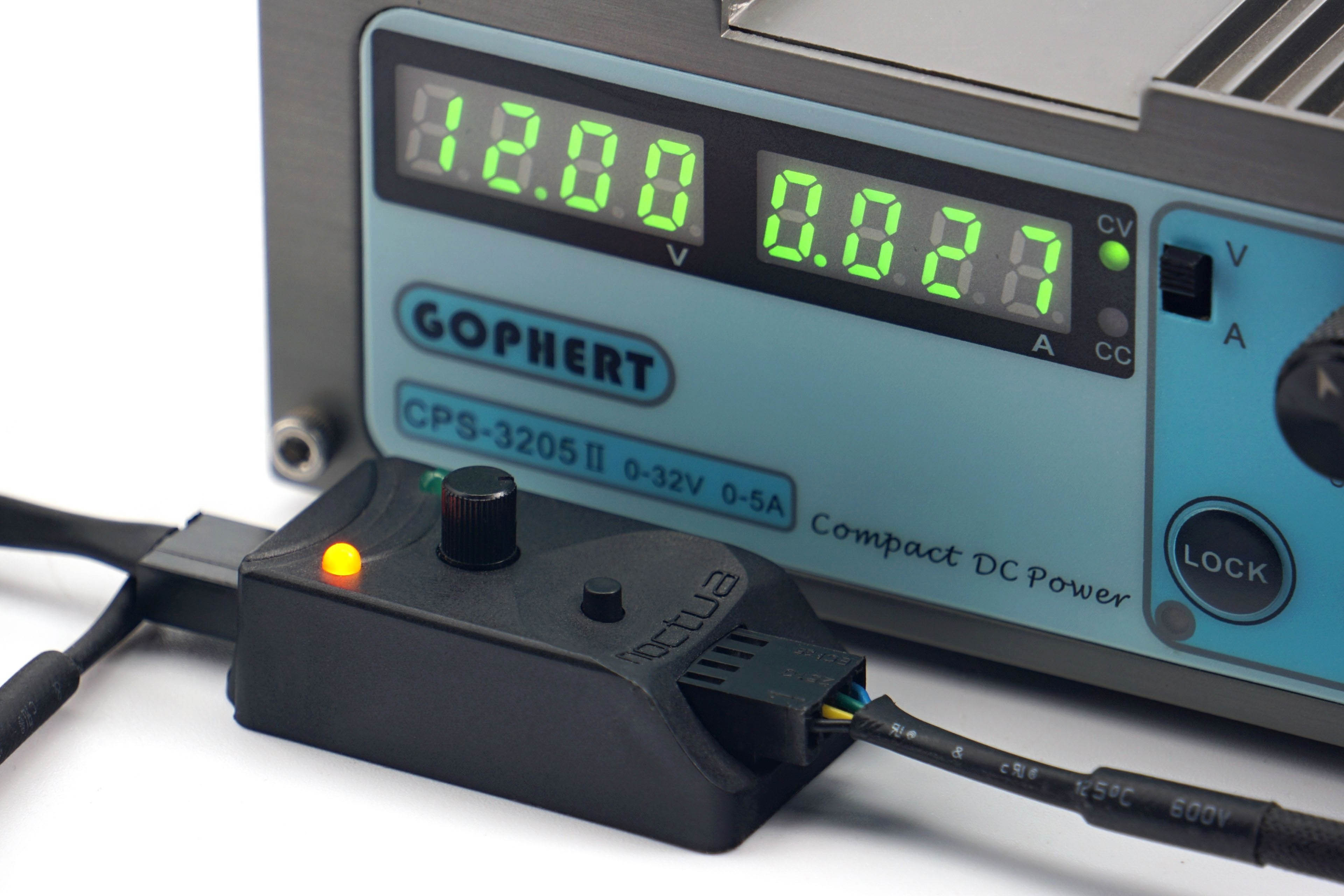
All fans are powered by Gophert CPS-3205 II laboratory power supply. It is passive and virtually noiseless, so it does not distort our noise level measurements. However, for the PWM fans, a Noctua NA-FC1 controller is connected through which the fans are regulated. We also have a shunt between the power supply and the Noctua controller. On it, we read the voltage drop, from which we then calculate the current. However, the voltage on the power supply is set so that 12 V goes to the Noctua NA-FC1. We then also set the exact 12 V to measure the maximum power of the 3-pin linear power supply fans.
In the power draw tests, we will be interested in the power draw in fixed noise level modes in addition to the maximum power consumption at 12 V or 100% PWM. That is, at those settings at which we also measure other parameters. Finally, in the graphs you will also find the power consumption corresponding to the start-up and minimum speeds. The difference between these two settings is that at start-up speed you need to overcome the frictional forces, so the power draw is always higher than at minimum speed. At these, the fan is already running and just reduces power to just before a level where it stops.

These start-up and minimum power draw data are a substitute for the start-up and minimum voltage information. You often encounter this when reading about fans, but with PWM fans there is no point in dealing with it. And although it is possible to power a PWM fan linearly, it will always perform better with PWM control – lower starting and minimum speeds. Therefore, it would be unfair to compare these parameters for all fans using linear control. That way, fans with PWM would be disadvantaged and the results distorted.
…and motor power
In addition to power draw, it is important to consider one more parameter that is related to the power supply – the power of the motor. This is usually listed on the back on a label and is often mistaken for power draw. However, the voltage and current indication here is usually not about power draw, but about the power of the motor. The latter must always be well above the operating power draw. The higher it is, the longer the life expectancy of the fan.
Over time and with wear, fan friction increases (through loss or hardening of the lubricant, dust contamination or abrasion of the bearings, etc.). However, a more powerful motor will overcome the deteriorating conditions of the fan to some extent, albeit at a higher power draw, but somehow it will cope. However, if the difference between the motor power and the operating power draw of a new fan is small, it may no longer be able to exert sufficient force to turn the impeller under increased friction due to adverse circumstances.

To test the power of the motor, we set the fan to full power (12 V/100 % PWM) and increase the mechanical resistance by braking the impeller in the middle. This is a higher load for the motor, with which the power draw naturally increases. But this is only up to a point, until the impeller stops. The power of the motor in our tests corresponds to the highest achieved power draw that we observed when the fan was being braked.
We use the Keysight U1231A high sample rate precision multimeters to analyse motor power (as well as normal operating power draw). In addition, the individual samples are recorded in a spreadsheet, from which we then graph the maximum. The final value is the average of three measurements (three maximums).
- Contents
- Arctic P14 Max in detail
- Overview of manufacturer specifications
- Basis of the methodology, the wind tunnel
- Mounting and vibration measurement
- Initial warm-up and speed recording
- Base 6 equal noise levels…
- ... and sound color (frequency characteristic)
- Measurement of static pressure…
- … and of airflow
- Everything changes with obstacles
- How we measure power draw and motor power
- Measuring the intensity (and power draw) of lighting
- Results: Speed
- Results: Airlow w/o obstacles
- Results: Airflow through a nylon filter
- Results: Airflow through a plastic filter
- Results: Airflow through a hexagonal grille
- Results: Airflow through a thinner radiator
- Results: Airflow through a thicker radiator
- Results: Static pressure w/o obstacles
- Results: Static pressure through a nylon filter
- Results: Static pressure through a plastic filter
- Results: Static pressure through a hexagonal grille
- Results: Static pressure through a thinner radiator
- Results: Static pressure through a thicker radiator
- Results: Static pressure, efficiency depending on orientation
- Reality vs. specifications
- Results: Frequency response of sound w/o obstacles
- Results: Frequency response of sound with a dust filter
- Results: Frequency response of sound with a hexagonal grille
- Results: Frequency response of sound with a radiator
- Results: Vibration, in total (3D vector length)
- Results: Vibration, X-axis
- Results: Vibration, Y-axis
- Results: Vibration, Z-axis
- Results: Power draw (and motor power)
- Results: Cooling performance per watt, airflow
- Results: Cooling performance per watt, static pressure
- Airflow per euro
- Static pressure per euro
- Results: Lighting – LED luminance and power draw
- Results: LED to motor power draw ratio
- Evaluation


Really, really interesting results.
I have heard that the P14 max suffers from motor noises, but it’s clear now that it’s only at <900 RPM where it's unstable.
The outer ring having almost no impact on noise profile is very surprising. Well, at least in the no obstacles environment. The huge impact of the ring on noise profile on radiators, despite having no effect otherwise, is even more surprising. Perhaps the back pressure cause deformation of the blades or something like that?
P.S. The links to radiator frequency plots are broken in the English version.
Thanks, fixed! 🙂
From the measurements on the fan frame, we know that the P14 Max is not a source of significant vibrations even at medium speeds, and yet the tonal peaks at low sound frequencies are quite high. We can assume that the vibrations on the blades will also be very weak and in a situation on a radiator, due to its resistance, the character of the vibrations may change. And they may move out of the unpleasant resonant frequencies. I guess it could be like this, that is, unless someone comes up with a more realistic theory. 🙂
Anyway, the fact is that the color of the sound on radiators is quite pleasant. That is, on our testing ones. Of course, you can’t generalise this.
The unpleasant tones that occur at certain RPMs are primarily from blade and frame spar resonance, and the source of their excitation is essentially unrelated to aerodynamic factors, and is primarily from the torque ripple of the motor. You can test the frequency of the anomalous tone at a particular RPM, and the RPM at which it occurs and the frequency of the sound wave will form some sort of mathematical relationship to the number of poles/coils in the motor (i.e., the frequency of the motor’s torque ripple) and the RPM at which the anomalous tone occurs won’t change, regardless of whether you increase the impedance or create a pressure pulsation that interferes with the blade’s aero-dynamics work.
Distinguishing a resonant noise from a blade or frame can be accomplished by observing a significant increase in frame vibration at the onset of the anomalous tone, and by observing a diminution of the anomalous tone when the frame tabs are pressed down.
However, note that in high speed (e.g., 4000+ rpm for 120mm fans) plastic impeller fans, the frequency of blade resonance rises slightly at high rpm due to pre-stress from blade deformation. The intrinsic frequency depends mainly on mass distribution and rigidity, and it is not easy to balance mechanical reliability and aerodynamic performance.
https://noctua.at/en/custom-designed-pwm-ic-with-scd
It would seem like this technology is a (partial) solution to this problem. Are there other ways of mitigation?
That wind tunnel looks great!