


Asus ROG Strix B760-I Gaming WiFi in detail
There are only a few models among the cheaper Mini-ITX motherboards for the Intel LGA 1700 platform. After testing the Gigabyte variant, the Asus ROG Strix B760-I Gaming WiFi is now here for review. This motherboard is designed for DDR5 memory and at the same time, we can still note its good affordability. Take a look at all that the Asus motherboard brings and how it fares in the tests.
Although clouds are already gathering over current motherboards for Intel (LGA 1700) processors – the arrival of LGA 1851 is already quite close – some models are better prepared for the later modernization. Those that support DDR5 memory. This is also the case with the Asus ROG Strix B760-I Gaming WiFi, which will not support the next generation of processors (Intel Arrow Lake), but the memory from a build based on it will be usable.
The ROG Strix B760-I Gaming WiFi motherboard’s support for the newer memory standard (DDR5) is one of the main differences from the recently tested Gigabyte B760I Aorus Pro DDR4 motherboard as well. The chipset (B760) is the same, but it supports “only” DDR4 memory, and although there is also a variant for DDR5 memory (Gigabyte B760I Aorus Pro), its availability is weaker and in some markets we can even talk about unavailability. In this regard (availability), the ROG Strix B760-I Gaming WiFi is better off, and when it comes to Mini-ITX boards from the “700” series, Asus doesn’t even bother with DDR4 variants. All models support DDR5 memory, and the older standard basically only concerns, as far as the LGA 1700 platform is concerned, the low-end models with H610 chipsets.
While it’s somewhat attractive to compare the ROG Strix B760-I Gaming WiFi to the Gigabyte B760I Aorus Pro DDR4, when you look at the comparable price, keep in mind that on the whole, the Asus board will cost you more due to the more expensive DDR5 memory, but the reward is a longer “lifespan” with regards to their usability when upgrading later. Of course, this aspect may not play any role if you are used to replacing the whole build anyway when the “old” one (with DDR4 memory) is no longer enough. So having that DDR5 memory that can eventually be used later may be only a theoretical advantage that someone may not take advantage of, while someone else may.
| Parameters | Asus ROG Strix B760-I Gaming WiFi | |
| Socket | Intel LGA 1700 | |
| Chipset | Intel B760 | |
| Format | Mini-ITX (170 × 170 mm) | |
| CPU power delivery | 13-phase | |
| Supported memory (and max. frequency) | DDR5 (7600 MHz) | |
| Slots PCIe ×16 (+ PCIe ×1) | 1× (+ 0×) | |
| Centre of socket to first PCIe ×16 slot | 92 mm | |
| Centre of socket to first DIMM slot | 56 mm | |
| Storage connectors | 4× SATA III, 2× M.2 (60–80 mm) PCIe 4.0 ×4 + PCIe 4.0 ×4 (42–80 mm) | |
| PWM connectors for fans or AIO pump | 3× | |
| Internal USB ports | 1× 3.2 gen. 2 type C, 2× 3.2 gen. 1 type A, 2× 2.0 type A | |
| Other internal connectors | 1× TPM, 1× ARGB LED, 1× RGB LED, 1× Clear CMOS jumper | |
| POST display | no (but has debug LED) | |
| Buttons | none | |
| External USB ports | 1× 3.2 gen. 2×2 type C, 3× 3.2 gen. 1 type A, 3× 3.2 gen. 1 type C, 3× 2.0 type A | |
| Video outputs | 1× HDMI 2.1, 1× DisplayPort 1.4 | |
| Network | 1× RJ-45 (2,5 GbE) – Intel I226-V, WiFi 6E (802.11 a/b/g/n/ac/ax) | |
| Audio | Realtek ALC1220P (7.1) | |
| Other external connectors | – | |
| Suggested retail price | 200 EUR |
Asus ROG Strix B760-I Gaming WiFi
This is the cheaper of the pair of Mini-ITX format models designed for the Intel LGA 1700 platform. In addition to the Strix B760-I Gaming WiFi, Asus also offers the Strix Z790-I Gaming WiFi, but at more than double the price. The cheaper and more attractive option for most users is probably obvious, although the Strix B760-I Gaming WiFi’s specs are naturally weaker.

The physical format has already been discussed – Mini-ITX (170 × 170 mm). Admittedly, after taking into account the cover around the I/O connectors, slightly protruding over the PCB, it’s more in height (175 mm), but only by 5 mm, which shouldn’t affect compatibility too much. Perhaps only in cases with a very small offset of the board from the side panel, where fans are expected. This may be the spot that will come into collision (with the fans) possibly first in such cases. But it also may not be, as this protrusion may be outside the axis of the design of the system fans.
The basic layout of the slots does not deviate from the conventions of Mini-ITX boards. There are two DIMM slots (with dual-channel support) for memory (DDR5), four SATA slots and traditionally one PCI Express slot (×16), in the fifth generation (PCIe 5.0). The board is forward-looking in this respect too, in terms of full support for next-generation graphics cards, and in the case of SSDs, the fastest available interface may come in handy even now.


The distance of the PCIe ×16 slot from the processor socket is above standard for Mini-ITX boards. From the center to the center of the PCIe and LGA 1700 sockets it is 92 mm. This spacing is sufficient for mounting even the largest (and widest) CPU coolers and avoid collision with an expansion card. And the greater the spacing of these components, the better the access to the PCI Express slot latch, which means more convenient removal of a typical graphics card.

However, the M.2 SSD slots only support PCIe 4.0. Both of the two that this motherboard has. On the slot connected to the CPU is a larger heatsink with a brightly colored ROG Strix print that also reacts spectacularly to light for the best visual perception, and looks a little different from every angle.

The second M.2 SSD slot (PCIe 4.0), also a four-lane slot, is on the back of the motherboard, where you need to pay attention to the height of a cooler. This can be as tall as the case, or its motherboard tray, allows. For some cases, there might be a cutout in these places, in which case the compatibility with SSDs with taller coolers should be better.

The power delivery for the processor has 13 (12+1) phases. These are cooled by two heatsinks, each characterized by a finned profile. And the grille of the cover between the VRM and I/O connectors is also noteworthy. This too will contribute to more efficient cooling by ensuring more intense airflow around the aluminum monoliths.


The MOSFET integrated circuits are Vishay SiC659 with the highest efficiency at a current load of around 10 A, that is according to the technical documentation. The VRM driver is the OnSemi ASP2100R.


The Realtek ALC1220 sound chip on the ROG Strix B760-I Gaming WiFi board will please those who find the ALC897 on the Gigabyte B760I Aorus Pro (DDR4) insufficient, for example.

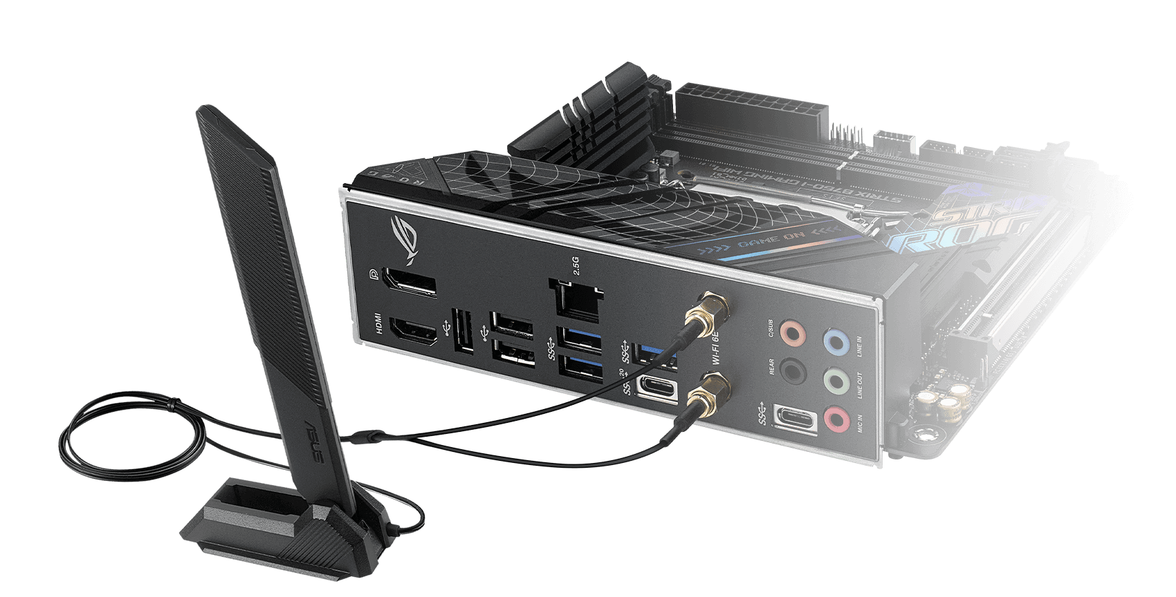
Almost in full configuration is also the external set of audio connectors. Next to the five 3.5-millimeter jacks, only the optical S/PDIF output is missing. In “its” position is a USB-C connector, the slower of the pair of external ones (with 5 Gbps). The fast USB-C gen. 2×2 port is already in the section between the rest of the USB connectors. In the version with the Type-A connector, there are six more USB connectors. Half of them standard 3.2 gen. 2 (i.e. with 5 Gb/s) and half of the slower 2.0 standard. These are suitable for connecting peripherals (keyboard, mouse, headset, multifunction device, …) that do not support faster interfaces (than USB 2.0).

Video outputs are in a fairly common two-connector configuration combining HDMI (2.1) and DisplayPort (1.4). There is one RJ-45 Ethernet connector, connected to a 2.5-gigabit Intel I226-V adapter. The board then also has WiFi 6E (Intel AX211), with two SMA connectors on the rear panel for the included antenna. This is a adjustable design with a stand for horizontal placement.
Please note: The article continues in following chapters.
- Contents
- Asus ROG Strix B760-I Gaming WiFi in detail
- What it looks like in the BIOS
- Methodology: Performance tests
- Methodology: How we measure power draw
- Methodology: Temperature and frequency measurements
- Test setup
- 3DMark
- Borderlands 3
- F1 2020
- Metro Exodus
- Shadow of the Tomb Raider
- Total War Saga: Troy
- PCMark and Geekbench
- Web performance
- 3D rendering: Cinebench, Blender, ...
- Video 1/2: Adobe Premiere Pro
- Video 2/2: DaVinci Resolve Studio
- Visual effects: Adobe After Effects
- Video encoding
- Audio encoding
- Photos: Adobe Photoshop, Affinity Photo, ...
- (De)compression
- (De)encryption
- Numerical computing
- Simulations
- Memory and cache tests
- M.2 (SSD) slots speed
- USB ports speed
- Ethernet speed
- Power draw without power limits
- Power draw with power limits
- Achieved CPU clock speed
- CPU temperature
- VRM temperature – thermal imaging of Vcore and SOC
- SSD temperature
- Chipset temperature (south bridge)
- Conclusion


As I understand it, the protruding I/O shroud violates the ITX motherboard specifications, and in some cases completely prevent the installation of the motherboard (for example, in the very compact Velka 3). In my opinion, it is a problem worth a negative bullet point in the conclusion part.
For ITX boards in particular, I hope it’s possible to test for cooler compatibility, especially some popular low-profile models (for example, Thermalright AXP90, AXP120, Deepcool AN600, Noctua L12S). Incompatibly to said coolers isn’t that big of a deal in typical systems, but can be a deal breaker for many SFF systems.
Socket position matters a lot too, not only in terms of potential interference between the cooler and the GPU, but also whether the cooler will protrude towards the top part of the motherboard, which can cause all sorts of issues (preventing installation of fans, bumping into power cords, or outright not fitting at all). So thank you for measuring this important metric. If possible, I suggest also providing the position in the X axis, as well as position of Y axis in terms of distance from the top end of the board.
Thanks for the insightful comments and additions to the article. In some PC cases the I/O shroud extending past the motherboard PCB probably really can be subject to collision. We will be using this board also in the new methodology for PC case tests and we still have to consider whether it would be appropriate to remove this shroud as a precaution to avoid possible collision with some (SFF) models, which would make them impossible to test. Anyway, I don’t know if it will really be as critical as we are discussing here. If you’ll notice, the I/O shield always overhangs the PCB (by those approx 5 mm), on all motherboards, including the Gigabyte B760I Aorus Pro (DDR4). The difference is that on the Asus motherboard, this PCB overhang extends more in the direction where I guess it can collide with the fans or with another element of the small case, in which everything is stacked a bit… tightly. However, this is not an isolated thing and the I/O shroud extends over the PCB like this on the MPG B760I Edge WiFi or even on motherboards of other/larger formats. It would probably be worth some caveat and consideration within the evaluation (and maybe the list of negatives), but I’m not sure how big of a “problem” it might be. And I’d hate to devote any more space to something than is appropriate. I mean, if the overhanging I/O shroud is going to cause incompatibility in one of 100 PC cases, then it doesn’t really matter that much. However, we don’t have that data on how many cases this “issue” will apply to, but it would certainly be appropriate to do some research on it.
Yes, precise control over the socket position is especially important for Mini-ITX boards (with regard to compatibility of larger coolers in SFF systems, as you write…) and we will be looking into it more in the layout analysis. That is, unless after a couple of boards we find that it doesn’t change too much. For example, the distance from the center of the CPU socket to the center of the first DIMM slot is the same on the vast majority of motherboards. In fact, I don’t think I’ve ever encountered a motherboard where it wasn’t 56mm. This might be a standardized thing? I confess I don’t know… I haven’t studied this to the last detail. 🙂
Thanks for the insightful comments!
–“…the distance from the center of the CPU socket to the center of the first DIMM slot is the same…”
Yes, this is mostly the same, but on the other hand, the distance of CPU socket in north/south direction varies a lot. I recently made ITX build in the SS Sugo 14. I wanted to install my old NH-U14S in it and I found out, that if I used Gigabyte B550I Aorus AX it wouldn’t be possible to install the right-side bracket (maybe with the offset).
On the other hand, ASRock B550M-ITX/AC has the CPU Socket moved 1 cm south, so in this case, it is OK (in fact, it is OK in both cases – with or w/o offset mount).
In my case, I have it mounted with the offset …despite what Noctua says.
”When used with the offset mounting position of the AM5 offset mounting kit, the cooler overhangs the top PCIe x16 slot. This issue can be resolved by using the standard (non-offset) position.”
my classic mistake, I have flipped the labels on the picture 😀 😀 …sorry
ASRock has a distance of 4.8 cm and Gigabyte only 3.8 cm from the north edge of socket to the north edge of MoBo.
Thank you for the additional information. For exactly the reason you describe, we list the dimension “Center of socket to first PCIe ×16 slot” in the parameter table for each motherboard. For coolers with a symmetrical base, it is then easy to calculate whether or not the CPU cooler will collide with an expansion card in the first PCI Express ×16 slot. For coolers with an asymmetrical base it’s worse, but as long as the manufacturer publishes a schematic with the dimensions…
–“…For exactly the reason you describe, we list the dimension “Center of socket to first PCIe ×16 slot” in the parameter table for each motherboard…”
Yes, that is perfect, 👍 … and the length from the center to the top edge of the MoBo (which is important, especially in SFF format) can be calculated (from it), but you could list it for lazy bastards like me 😛
So I’ve been looking into the specifications and came to this excellent summary (https://www.overclock.net/threads/guide-to-drawing-pci-e-and-atx-mitx-rear-io-bracket-for-a-custom-case.1589018/). The I/O shield aperture (i.e. opening) extends 2.44 mm from the motherboard area. There’s an additional 2.54 mm keepout zone surrounding the I/O shield, reserved for the lip for proper mounting. What isn’t clear, however, is if this 2.54 mm may be used other motherboard components that are not the I/O shield.
In any case, this ASUS board (and some others) has taken the stance of “we can use this 2.54 mm for heatsinks”, and Velka 3 is designed around the assumption that this 2.54 mm is only for the I/O shield and nothing else, which lead to incompatibility issues like this (https://www.reddit.com/r/sffpc/comments/t9ab51/on_asuss_oversizednoncompliant_miniitx/). Perhaps we can do more digging into who’s in the right here…
Most floor plans depicted the I/O space as a safety area without further specification. From my perspective, It is primarily a manufacturer oversight, as they do not account for the need for a small additional space.
Additionally, you can see that the 0.1″ keep-out zone surrounding the I/O shield in the rear view is specified as minimal.
Thank you for the link.
Page 14:
“The 0.1″ (2.5mm) keepout zone around the I/O aperture area is required in an ATX 2.2-compliant chassis (Figure 4). This allows ATX 2.2-compliant I/O shields to fit into ATX 1.1 or 2.2-compliant cases. The keepout area is needed for the shield attachment points. Avoid paint application in this area.”
“0.100 MIN KEEPOUT AROUND OPENING”
“Do not place any topographical features in this area on either the inside or outside surface. Avoid paint application in this area.”
All wordings, to me, imply that this keepout zone is strictly meant for the case panel surrounding the I/O shield, and is not meant to extend to other parts of the I/O area. Thus, the non-compliant thing here is the ASUS board(s), not Velka 3.
The area should remain clear throughout, as depicted in the top view (detailed layout), to ensure easy installation and for maintenance purposes. The rear bracket could be integrated as a fixed component of the motherboard. In my opinion, the case manufacturer has underestimated the need for adequate space. They are reducing the size too much.
As Ľubo suggested, this type of I/O block has been on the market for several years, so I believe it’s the case manufacturer’s flaw. You can’t rely solely on specifications; you need to consider existing solutions on the market.
Look at the 2015/2016 Z170 boards, five of eight used probably the same area for I/O block.
Maybe it wasn’t clear, but it is at least a 6-year-old discussion about integrated shields. As we know, the space surrounding them can vary according to the original specifications. I’m done for now, I promise 😅
It can be quite misleading to look from the front of the motherboard due to perspective. To confirm whether there’s anything protruding from the board area, it’s best to look from the bottom side.
I decided to check the first page recent motherboards reviewed by TPU to see which boards have protrusions from the board area and which do not (I wanted to include all links but it was detected as spam, so I’ll just post a few examples). No boards other than ASUS’ have protruding elements. 2 out of 3 tested ASUS boards have protrusions.
Does not protrude:
https://www.techpowerup.com/review/gigabyte-x670-aorus-elite-ax/3.html
Protrudes:
https://www.techpowerup.com/review/asus-rog-crosshair-x670e-hero/3.html
So is it an ASUS problem? Let’s look into 9 more ASUS boards: 6 out of 9 protrudes. It seems ASUS really like to have the protruding elements on boards with integrated I/O shields.
Final bonus: do the Z170 boards have protrusions? At least for the boards shown in your image, no. (The last two were skipped because they obviously are not protruding).
https://www.kitguru.net/components/motherboard/luke-hill/asus-maximus-viii-hero-z170-motherboard-review/3/
Sorry for the long comment, I’m just really interested in this topic😅
Thanks for the comment! You can always post comments with whatever links you want. It will never be spam. It’s just our “dumb” filter, haha, that evaluates it that way, and if a comment doesn’t get published right after it’s written, I’ll always approve it manually. Hopefully we can somehow optimise that “spam filter” more sensibly, so that it only blocks really inappropriate, downright advertising comments and always lets the informationally enriching ones through, regardless of whether or not they contain critical links. I’m pretty sure that’s too complicated for me and we’ll have to get advice from someone who has experience in this area. So, for the time being, with the withheld comments, let’s call them that, it’s always going to be about manual approval…
You are right; the picture of the Z170s doesn’t show any of the protrusions we discussed. The perceived protrusion was for sure a result of perspective distortion. I made a mistake due to vague memories about the early solutions of the integrated I/O shield. Indeed, Asus has recently extensively used this option.
However, my attitude remains the same. Manufacturers like Velka seem to be pushing miniaturization too far. How many customers would be concerned by an additional 1 cm of space? Their efforts seem irrational to me. So, I’m not and won’t be their customer.
In my opinion, both are true – Velka is pushing miniaturization a bit too far, and ASUS is also violating the spec for no good reason (just to make the board… look better when viewed from top? I don’t know…)
I think Velka 3 is a case with too much compromises too (only 37 mm cooler clearance, strictly 2-slots only, no space to avoid turbulent noises), but from these designs you can see that that design philosophy is “small size over everything else”. And as far as I know, ASUS hasn’t made ITX boards with protrusions like that before Intel 6xx series, so I can’t really fault them on this given that the case was designed before that.
Maybe I am a bit biased against ASUS, but I have seen too many of their recent boards that add useless things just for “aesthetics”. There were some boards so bad that even the U12A cannot fit, because they’re using purely decorative plastic pieces over their VRM heatsinks that interfere with the cooler. There’s also their B550I board which was good, but had issues with RTX 40-series that they refused to fix even now, which makes me think they don’t really care about SFF users.
For the spam stuff, my initial reply probably contained so many links that I got a “rejected as spam” message😅 I don’t think that version even passed through enough to be able to be manually approved.
You’re right; the justification for altering a settled form of I/O block should be rational, not merely for aesthetic reasons. But I still believe that integrating the rear bracket/shield is a valid reason.
About the problem with spam-marked links: HWC typically approves comments containing problematic links and notifies users about the process. Occasionally, however, posted links are flagged as spam, leading to an error page. This may be due to a blacklist in the backend that the editor can’t easily manage.
Per this comment on SFF network (https://smallformfactor.net/forum/threads/consistency-of-location-of-a-cpu-socket-relative-to-the-board.17419/post-262562), socket position isn’t fixed, so you find quite a bit of variation in the north-south axis. As for the east-west axis, there probably is some variation, but that axis is very cramped (I/O, socket, RAM, cable connectors) so there isn’t much option there. As for the distance between the socket and RAM, as I understand it, the minimum distance is mandated by the socket. Meanwhile, everyone wants the shortest distance for best latency and stability, so it is effectively a fixed value.
On some pages (32 and 33), the data for this board seems missing, but there are two entries of ROG Strix Z790-A Gaming WiFi II with one being highlighted in red. Is the highlighted data supposed to be the data for this board?